Navigation

The WGS-84 Ellipsoid (not to scale)
By Cmglee, CC BY-SA 4.0, via Wikimedia Commons
WGS-84 became the de facto standard for satellite navigation after its adoption by the Navstar Global Positioning System (GPS) and the USA’s 1983 permission for civilian use.
U.S. President Ronald Reagan permitted civilian use of GPS after the airliner KAL 007 was shot down by Soviet interceptor aircraft. The aircraft had strayed into prohibited airspace due to a navigation error.
As a result, modern aircraft navigation standards require aircraft to follow geodesic segments on the WGS-84 ellipsoid. See RTCA DO-283C / Eurocae ED-323.
2D Navigation
Despite the widespread adoption of WGS-84, many systems still perform navigation calculations on 2D map projections, see map projection.
The high accuracy of satellite navigation is lost in the inherent distortions of 2D map projections.
3D Navigation
We needed accurate, efficient navigation software for our conflict detection solution, so we developed our own 3D navigation software libraries for spherical and geodesic geometries.
Open source navigation software
Our 3D navigation software is available in the following open source Rust crates and GitHub repositories:
| Description | Rust Crate | Github Repo | C++ / Python Repo |
|---|---|---|---|
| Geometric calculations on the WGS84 ellipsoid | icao-wgs84 | icao-wgs84-rs | via-ellipsoid-cpp |
| Geometric calculations on the surface of a sphere | unit-sphere | unit-sphere-rs | via-sphere-cpp |
| Trigonometry calculations | angle-sc | angle-sc-rs | via-angle-cpp |
| Air Navigation units defined in ICAO Annex 5 | icao-units | icao-units-rs | via-units-cpp |
All the libraries are open source and available under the MIT License.
Map projection

The 1st F-22A Assigned to the 27th Fighter Squadron
US Air Force public domain
Traditionally, navigators plotted courses as straight lines on flat paper charts, i.e., on map projections of the Earth’s surface.
For example, the Mercator projection was originally developed to aid navigation with a magnetic compass. A straight line on a Mercator chart represents a path of constant bearing, known as a rhumb line.
Unfortunately, all map projections distort the Earth’s surface, since it is impossible to represent a 3D surface in 2D without distortion.
Antimeridian Cutting
World maps are usually centred at the prime meridian and cut the globe along the ±180° meridian, called the antimeridian.
Geospatial standards such as RFC 7946, “The GeoJSON Format, require that:
“Any geometry that crosses the antimeridian SHOULD be represented by cutting it in two such that neither part’s representation crosses the antimeridian.” RFC 7946 Section 3.1.9.
Antimeridian cutting may be acceptable for drawing objects on a map.
However, it can be dangerous for global navigation because it introduces a discontinuity at the antimeridian.
See: Navigational software glitch forces Lockheed Martin F-22 Raptors back to Hawaii.
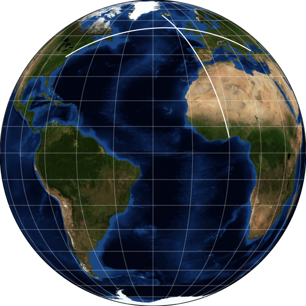
Spherical geometry

A great circle plane and 3D pole vector
The Earth is almost a perfect sphere (the flattening of the WGS-84 ellipsoid is just over 1/3%).
Modelling the Earth as a sphere is good enough for many purposes and eliminates the antimeridian cutting issue of map projections.
Navigators have modelled the Earth as a sphere for centuries. For example, the shortest (great circle) distance between two points can be calculated using the Haversine formula in spherical trigonometry.
3D Vectors
A sphere can also be modelled by 3D vectors:
- a point on the surface of a sphere can be represented by a vector from its centre,
- and the pole of a great circle can be represented by a vector from the centre of the sphere, perpendicular to the great circle plane.
Many navigation solutions are simpler using spherical 3D vectors than planar 2D vectors. For example, the intersection of two great circles can be calculated simply from the cross product of their pole vectors.
Modern computers, both CPUs and GPUs, are optimised for 3D vector operations because of their widespread use in computer graphics. Linear algebra libraries such as nalgebra and eigen exploit these optimised operations, enabling fast, efficient 3D vector navigation calculations.
Spherical vector geometry
Geodesic geometry
Intersecting geodesic paths
Unlike straight lines and great circles, geodesics are non-linear, which makes tasks such as distance calculation more complicated.
Current navigation standards RTCA DO-283C / Eurocae ED-323 recommend Vincenty’s formulae.
Thaddeus Vincenty published his formulae in 1975. They are usually accurate to within a millimetre, but the iterative techniques often require many iterations and do not always converge to a solution.
Charles F. F. Karney reformulated Vincenty’s formulae in 2013 to produce formulae that are:
- more accurate,
- require fewer iterations,
- and always find a solution.
Karney’s formulae are widely recognised as the most accurate geodesic formulae available today.
Karney’s 2023 paper Geodesic Intersections provides a complete solution to the intersections of two geodesic paths on the surface of an ellipsoid. For example, it considers the issue of coincident geodesic paths, which previous algorithms had overlooked, such as Baselga and Martinez-Llario’s 2017 paper: Intersection and point-to-line solutions for geodesics on the ellipsoid.
Geodesic algorithms
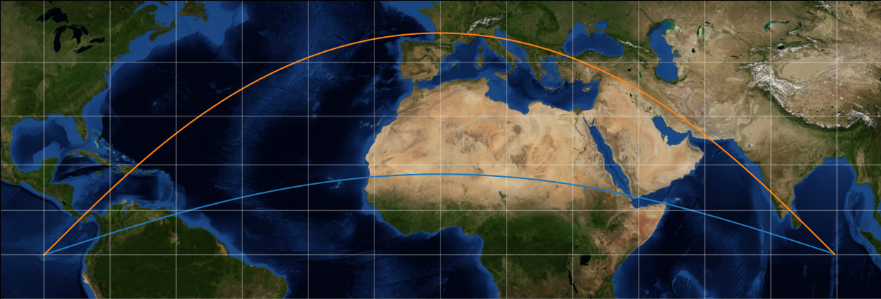
Geodesic (orange) segment and great circle (blue) arc
Our geodesic algorithms combine Karney’s Geodesic Intersections algorithms with spherical vector geometry to calculate:
- Along Track Distance (ATD) relative to a geodesic segment;
- Cross Track Distance (XTD) from a geodesic path;
- and distances along two geodesic segments to their closest intersection point.
Our navigation software implements these algorithms on the WGS-84 ellipsoid.
Geodesic algorithms
Contact us